GI7b Linear
This page shown only for historical reasons, the amplifier is no longer in my possesion, but has found a new home at OZ6YM!
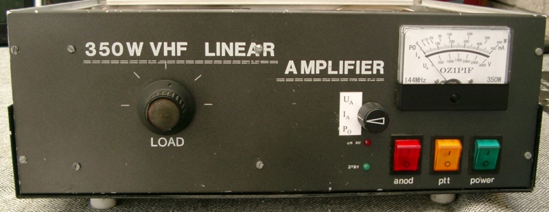
The saga about my 144 MHz GI7b Linear:
In 2000 I acquired a second- (third or fourth) hand job, originally built by HG8UG, bought in DL-land from DG5NFF (I believe) by OZ1BNN last year.
Although it would deliver the power when just started, it got extremely hot while doing so, required constant retuning as temperature changed, and last, but not least, after some hours intensive contest use, it would only deliver about 250W or so, where it should be able to give some 350W+!
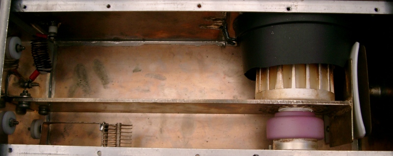
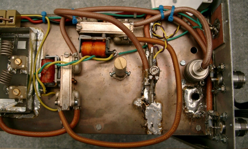
The refashioned Plate compartment with flower-pot "chimney" and new plate-line
A close inspection showed that a lot of hot air recirculated within the enclosure, not enough air was passing the anode cooling fin, and last but not least: the anode line was made of 3mm aluminium, with a poorly fitted tuning stator fastened to it by two steel screws. On dismantling it turned out that at some time a tube had been secured poorly to the anode line (apparently not the current one, which had no marks) resulting in it being very badly pitted where it contacts the anode, resulting in a very poor electrical AND heat contact between them.
First, on inspiration from G3MY, I fashioned a chimney from a flower pot to direct the air from the fan on to the anode. I doubled the area of the exhaust opening in the cover, and drilled 58 additional 5mm holes along the left edge of the cover, to let air passing the grid get out directly.
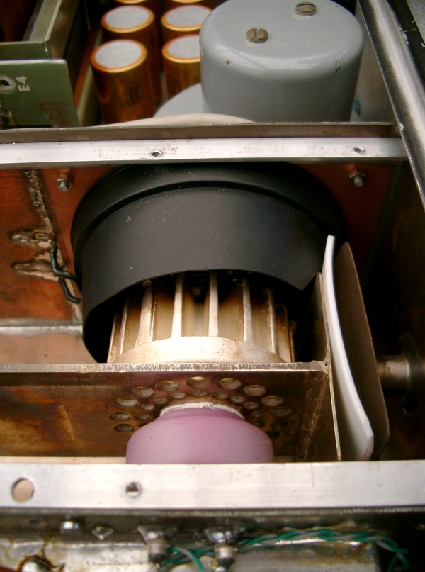
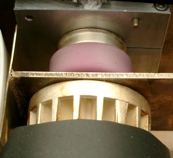
Close-up of tube end.
I then constructed a new anode line from 3mm brass, with the stator (made from 1mm brass) brazed on. I drilled two concentric circles of 18 holes each, the outer Ø 6mm and the inner Ø 4mm, to let air pass dirctly through the anode cooler and through holes in the grid block. Finally, for good measure, the whole thing was silvered electrolytically!
New plate-line decoupling capacitor, the old one was made from a piece of glass fiber PCB board and was partially burnt! Got very very hot. I estimate that some 50-100W was dissipated in it = pure loss!
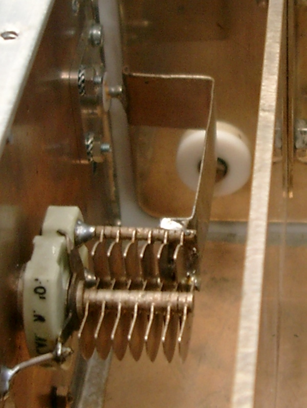
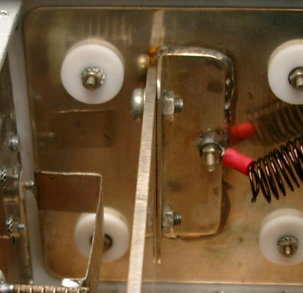
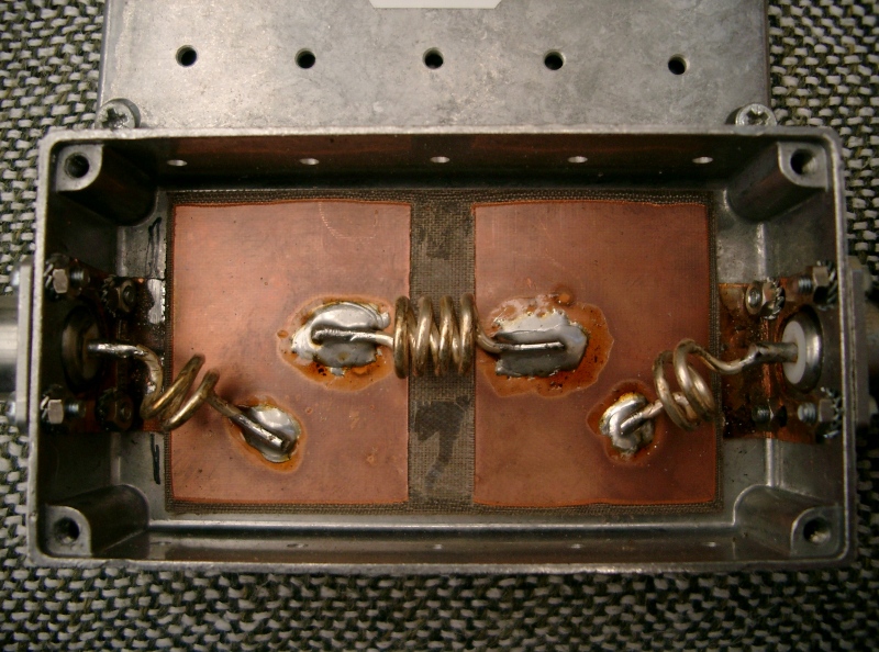
Output coupling and load tuning
New tube socket made from 10mm Aluminium.
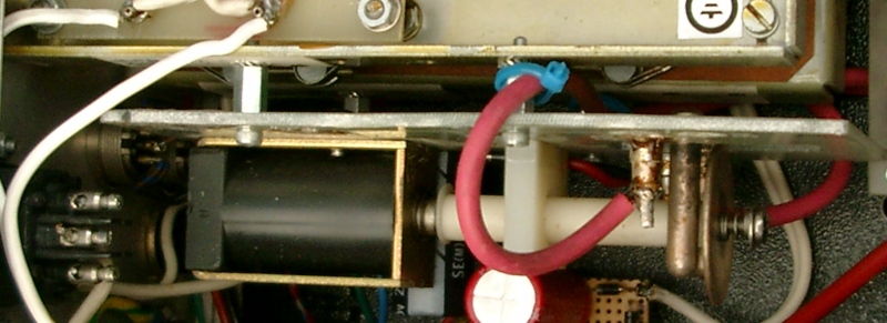
HV relay added, originally HV was switched on/off with switch on front (rated for 250V NOT 2KV!)
Coax relays replace original "Washing-machine" type.
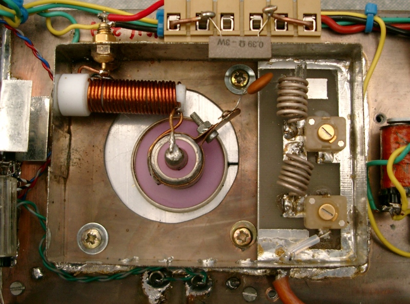
Socket from Cathode side, note 0.39 Ohm resistor to adjust heater voltage!
And
of cause - you don't run a power amplifier without a decent LP filter - do
you? This filter built from a design by AF9Y.
I'm happy to report, that the linear is now very stable, will deliver almost 400W key-down, and requires no retuning after initial warm-up, and it'll deliver full power even after extended abuse. It also runs a lot cooler!
Some links to more GI7b information:
http://www.uksmg.org/russia.htm