FL2000B -> FL2000/QB Conversion

NB! Click on this or any other picture to see the large size version!
My problems started when the old 572Bs had to be replaced by the more
lively
Svetlana tube. I do not recommend you to use the this tube, I went through
two sets in fairly rapid succession, before I threw the towel in the ring.
My FL2000B is now happily clicking along with a single QB-4/1100, giving
some 600W+ on the lower bands, and about 500W on 10m, something that it
never could manage with the 572Bs, and being absolutely 100% stable and easy
to tune.
Well, if you're only going to use the amp for 80, you'll probably not have
too much grief, my problem bands were 10 and 15.
Total cost of conversion: less than US$100! including new transformer,
vacuum relay and socket!
IMHO the 572B is totally unsuitable for RF amplification (at least as far as
the Svetlana version is concerned), it is far too temperamental and prone to
take off on its own, instanstantly destroying the tube(s).
The QB series of tubes are European zero-bias glass-envelope tetrodes,
suitable for use in GG conf. Both types mentioned below are suitable for
this conversion:
QB-3.5/750 = 6156 (Eimac)
QB-4/1100 = 7527 (Eimac)
They are readily available as pulls from commercial equipment. I paid $10
for the QB-4/1100, and I have 2 QB-3,5/750 I got for free. They are
virtually indestructible, one of the 3,5/750s I have, has been in continous
commercial 24h service for 10 years and still delivers full output!, they
will also withstand considerable abuse (HV, temperature and peak I).
(BTW: By changing a jumper in an L4B you can also use these tubes in lieu of
the 3-500Zs, which should give a fairly good image of the tubes and their
capabilities)
Don't try to put in a bigger PS, the switch assembly is marginal already,
and you'll have to be fairly creative to patch in 160m. I had to abandon the
deck used for switching in 100pF on the plate cap, because it repeatedly
arced out on me. (With the QB in place and probably somewhat higher tank Q)
I finally used it for switcing a vacuum relay, which switched the 100pF.
Interestingly, the fireworks always happened on 40m!
With a pair of new Svetlanas, AND VERY careful tuning (SIC), I managed to
measure 750W out on 80m, BUT it took a lot of fidling, I never saw
more than
500W on 20, 400W on 15m and less than 250W on 10m! and even that was
diffucult to achieve.
With the QB-4/1100 and basically the same tank (more load C on 40 and 80),
I get 600+ on 80-20, 550 on 15 and 500W on 10, and
it has become a very tractable beast indeed. This is in GG conf. with G2
firmly grounded. I have no doubt that by lifting G2 to some 50-100V DC,
you'll get at least 3dB more gain, but I felt conservative and I'm very
happy with what I have now.
I also ripped out the old filament transformer, the electrolytics and
diodes, putting in better diodes, double the capacity, and a suitable
filament transformer for the QB.
Don't throw out the HV transformer, it's very good quality, and certainly
not at fault. The
electrolytics though...., after 30+ years of service or rest, they certainly
deserve retirement :-)
I'm using the two 100V primaries in series, fed from our 230V system, resulting in about 2900V idling, falling to some 2700V when going full tilt (Key down)!
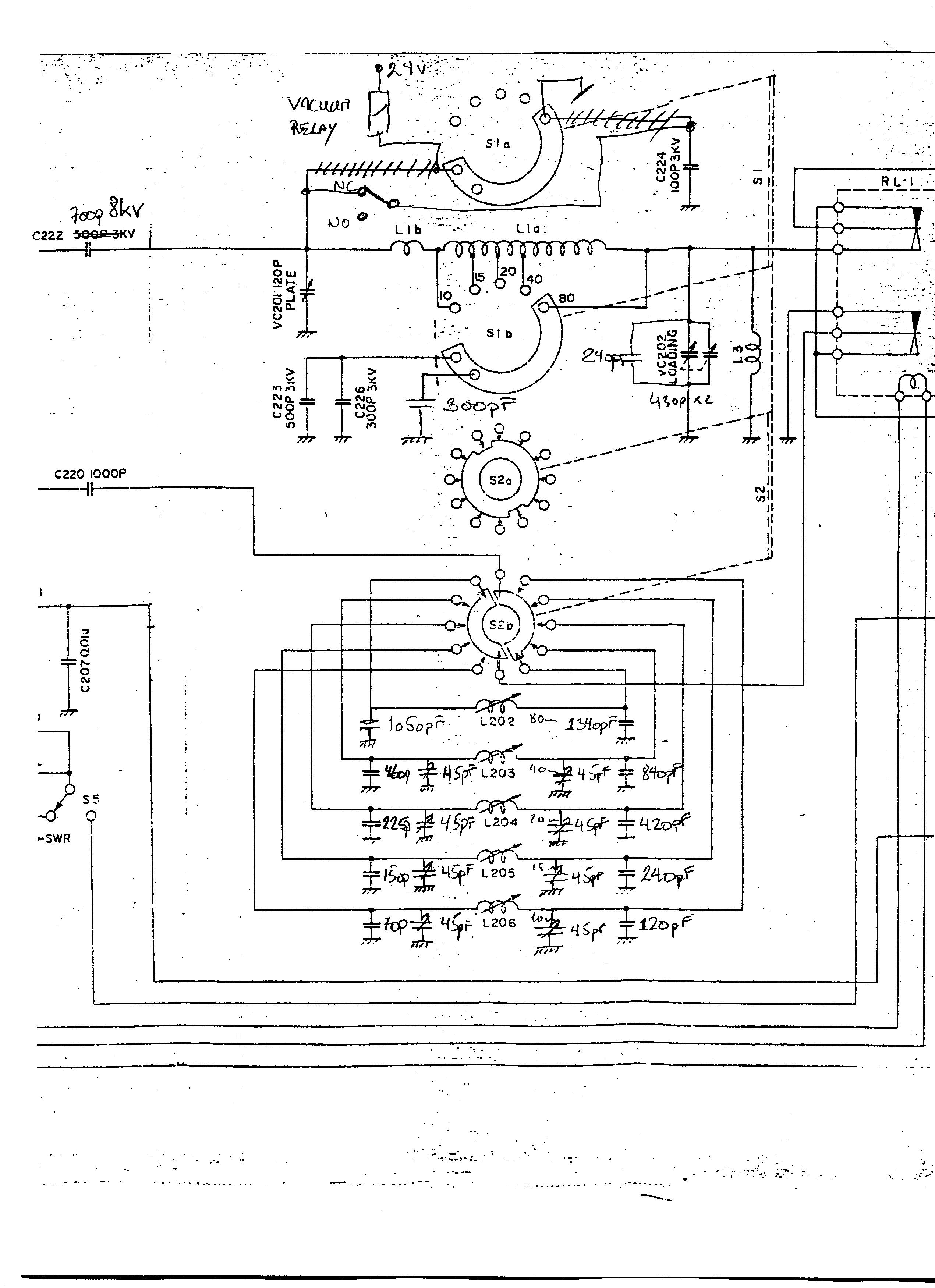
I realize that I still have to do some schematics of the mods, but I'm hesitating to show you my sketches - I'm no draftsman - to put it mildly! In the meantime, here are the essentials pencilled in in the original:
Medium size (125KB) and Large size (690KB)
And now to the pictures:
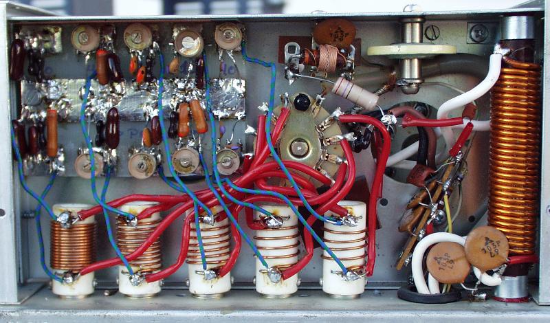
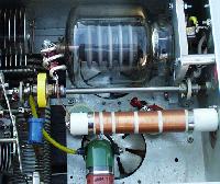
This is the cathode compartment with the new input matching circuit board in place.

Close-up of the input matching.
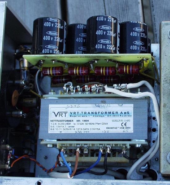
The new filament transformer and electrolytic board with bleeders.
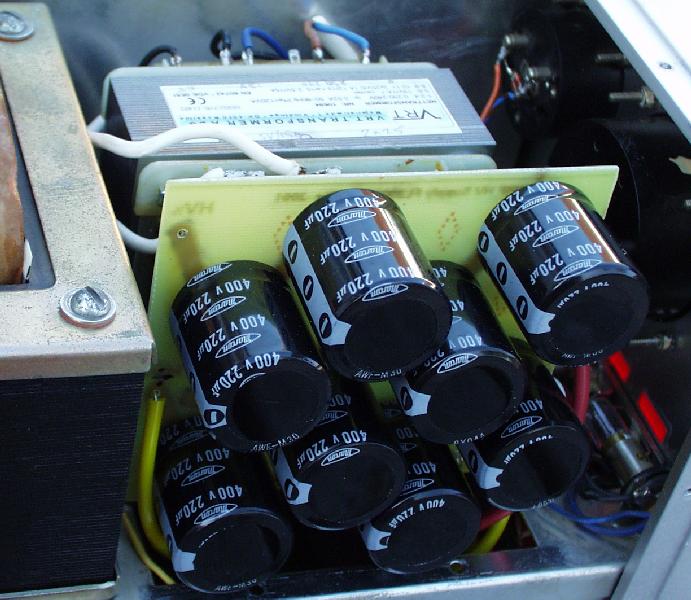
The bank of 8 220uF/400V electrolytic capacitors
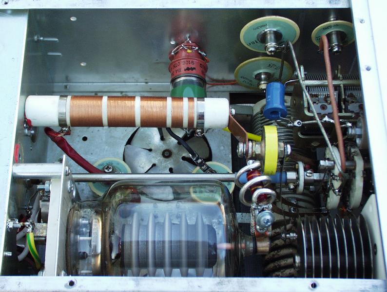
This is where it all happens! The tube in place with beefed-up isolation cap and parasitic suppressor.
Same from another angle.
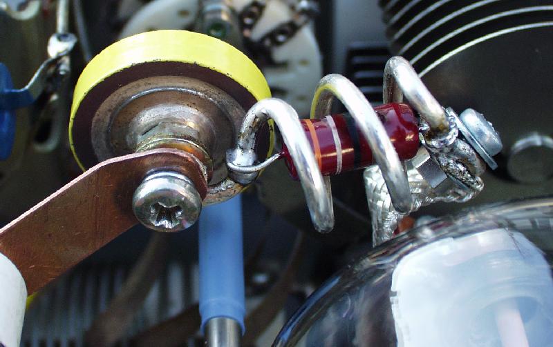
Close-up of cap/suppr. assembly.

The rearranged and additional load C.
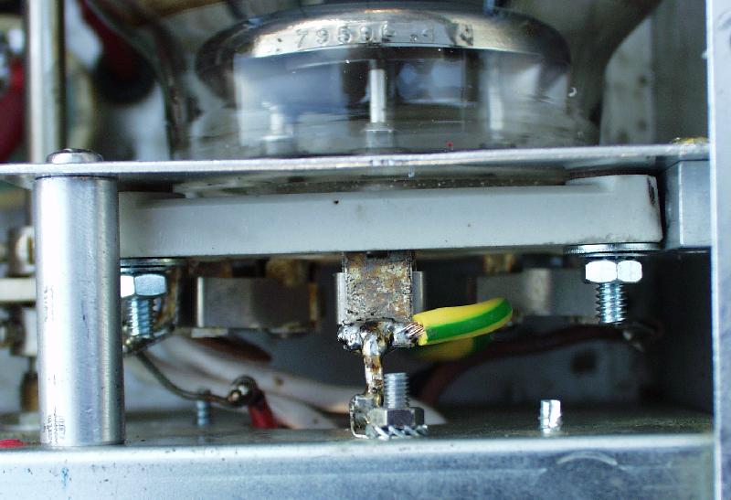
The socket assembly.

Bottom view with rectifier board (original version, now replaced!)
Good luck with your conversion effort, it is now a very nice little amp.